Introduction to Triac:


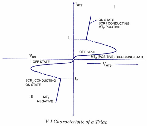
A TRIAC has three terminals viz MT1, MT2, and G, and is a five-layer semiconductor device. It is a switching device similar to SCR(Silicon Controlled Rectifier). Still, it can conduct in both directions since it is made by combining two SCR in an anti-parallel state. Effectively, a TRIAC is equivalent to two SCRs. Some common examples include BT136 TRIAC and BTA41 TRIAC.
You may wonder if TRIAC is unidirectional or bidirectional. It is a bi-directional device the current can either flow from MT1 to MT2, or from MT2 to MT1 when the gate terminal is triggered. MT1 and MT2 can be positive or negative with respect to each other and the gate.
There are four different modes of operations:- When MT2 and Gate are positive with respect to MT1
- When MT2 and Gate are negative with respect to MT1
- When MT2 is Positive but Gate is Negative with respect to MT1
- When MT2 is Negative but Gate is Positive with respect to MT1

Also read: Difference between DIAC and TRIAC.
Also read: Difference between SCR and TRIAC.
Introduction to MOSFET:


As discussed earlier at the start of this blog, MOSFET stands for Metal Oxide Semiconductor Field Effect Transistor. A MOSFET has three regions:
- Source(S)
- Drain(D)
- Gate(G)
It can be constructed from of a doped semiconductor. The two regions, the source and the drain, are placed on top of the doped semiconductor. Between the source and the drain, there is an oxide layer that acts as an insulator. On top of the oxide layer, there is a metal plate to put the gate structure, so the name has metal oxide.
The gate region is placed on top of the insulating oxide layer. This makes the gate to be electrically isolated from the rest of the circuit. However, it being electrically isolated does not prevent it from being able to control the flow of current from the source to the drain.
When a voltage is applied across the gate and source, an electric field is established to control the conducting path between the source and the drain. This is why a MOSFET is a voltage controlled device and a type of F.E.T. The arrow on the symbol of MOSFET indicates the direction of electrons. The body effect in MOSFET happens when the substrate or body of the transistor isn’t biased at the same level as the source. The corresponding voltage difference between source and body can lead to an increase or decrease of the threshold voltage.
A few examples of MOSFET include IRFZ44N MOSFET and IRFP264N.
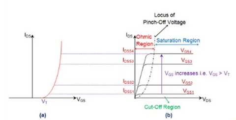
Transfer Characteristics of MOSFET
The output characteristics of a MOSFET is a plot of Id as a function of Vds with Vgs as a parameter.

Also read: Difference between JFET and MOSFET
Difference between TRIAC & MOSFET:
| TRIAC | MOSFET |
| 3 Terminals, MT1, MT2, and Gate | 3 Terminals, Source, Drain and Gate |
| Current-driven device | Voltage-driven device |
| Self-sustaining | Not self-sustaining |
| Can switch AC and DC | Can only switch DC.DC |
Applications & Uses:
| TRIAC | MOSFET |
| Illumination and temperature control | Switching and amplifying electronic signals |
| Controls AC power | Used as an Inverter |
| Controls motor speed and also as a static switch for AC (On/Off) | Used in digital circuits |


