

As many people have many doubts regarding which GSM module to use, why there is a lot of price difference, how will the pins be connected, on which communication protocol do they work, so here in this blog, all the doubts will be cleared one by another.

SIM800L GSM/GPRS module is a miniature GSM modem, which can be integrated into a great number of IoT projects. You can use this module to accomplish almost anything a normal cell phone can; SMS text messages, make or receive phone calls, connect to the internet through GPRS, TCP/IP, and more! To top it off, the module supports quad-band GSM/GPRS network, meaning it works pretty much anywhere in the world.
The SIM800L is a GSM module from Simcom that gives any microcontroller GSM functionality, meaning it can connect to the mobile network to receive calls and send and receive text messages, and also connect to the internet using GPRS, TCP, or IP. Another advantage is that the board makes use of existing mobile frequencies, which means it can be used anywhere in the world.
Hardware Overview of SIM800L Module
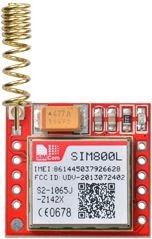
At the heart of the module is a SIM800L GSM cellular chip from SimCom. The operating voltage of the chip is from 3.4V to 4.4V, which makes it an ideal candidate for a direct LiPo battery supply. This makes it a good choice for embedding into projects without a lot of space.

The SIM800L GSM chip's data pins have all been split off to 0.1 pitch headers. This comprises the pins needed for UART communication with a microcontroller. With Auto-Baud detection, the module supports baud rate ranging from 1200bps to 115200bps.
To connect to a network, the module requires an external antenna. The Helical Antenna is normally included with the module and solders directly to the NET pin on the PCB. If you want to keep the antenna away from the board, the board also offers a U.FL connector.
On the back, there's a SIM slot! Any 2G micro SIM card that has been activated will function fine. On the surface of the SIM socket, the precise direction for inserting a SIM card is usually inscribed.

This module measures only 1 inch² but packs a surprising amount of features into its little frame. Some of them are listed below:
-
Supports Quad-band: GSM850, EGSM900, DCS1800 and PCS1900
-
connect onto any global GSM network with any 2G SIM
-
Make and receive voice calls using an external 8Ω speaker & electret microphone
-
Send and receive SMS messages
-
Send and receive GPRS data (TCP/IP, HTTP, etc.)
-
Supports FM
-
Supports PWM
-
Transmit Power:
-
Class 4 (2W) for GSM850
-
Class 1 (1W) for DCS1800
-
Serial-based AT Command Set
-
FL connectors for cell antennae
-
Accepts Micro SIM Card
-
There is an LED on the top right side of the SIM800L Cellular Module which indicates the status of your cellular network.
Selecting Antenna
To utilise the module for voice or data communications, as well as some SIM instructions, you'll need an antenna. As a result, picking an antenna could be critical. You may add an antenna to your SIM800L module in two ways.
The first is a helical GSM antenna, which is normally included with the module and connects to the NET PIN on the PCB. This antenna is ideal for applications that require minimal area yet struggle to maintain communication, particularly if the project is being carried out indoors.
The second one is any 3dBi GSM antenna along with a U.FL to SMA adapter. You can snap-fit this antenna to a small u.fl connector located on the top-left corner of the module. This type of antenna has a better performance and allows putting your module inside a metal case – as long the antenna is outside.

SIM800L Pinout Configuration
|
Pin Number |
Pin Name |
Description |
|
1 |
NET |
External antenna attachment pin |
|
2 |
VCC |
Power supply pin, 3.4V to 4.4V input |
|
3 |
RST |
Reset pin, pull low for 100ms to perform hard reset |
|
4 |
RXD |
Serial data input |
|
5 |
TXD |
Serial data output |
|
6 |
GND |
Module ground reference |
|
7, 8 |
SPK |
Speaker differential output |
|
9, 10 |
MIC |
Microphone differential input |
|
11 |
DTR |
Serial data terminal ready pin, pull high to enable sleep mode |
|
12 |
RING |
Interrupt output, active low |

SIM800A is a Dual-band GSM/GPRS module that works on frequencies EGSM 900MHz and DCS 1800MHz. SIM800A supports GPRS multi-slot class 12/ class 10 (optional) and supports the GPRS coding schemes CS-1, CS-2, CS-3 and CS-4. SIM800A is designed with a power-saving technique so that the current consumption is as low as 0.55mA in sleep mode.
With a tiny size, it can fit into the slim and compact demands of custom design. Featuring an Embedded AT, it allows total cost savings and fast time-to-market for customer applications.
The SIM800A modem has a SIM800A GSM chip and RS232 interface which enables easy connection with the computer or laptop using the USB to the Serial connector or to the microcontroller using the RS232 to TTL converter. Once you connect the SIM800A modem using the USB to RS232 connector, you need to find the correct COM port from the Device Manager of the USB to Serial Adapter.
Then you can open Putty or any other terminal software and open a connection to that COM port at 9600 baud rate, which is the default baud rate of this modem. Once a serial connection is open through the computer or your microcontroller you can start sending the AT commands. When you send AT commands for example “ATr” you should receive back a reply from the SIM800A modem saying “OK” or other response depending on the command sent.
Power Supply
The power supply of SIM800A ranges from 3.4V to 4.4V, and 4.0V is recommended. It must be able to provide sufficient current up to 2A for the high-power transmitting. If the DC input voltage is +5V and if no issue with the power efficiency, a high-current low-dropout regulator is recommended.
SIM800L Pinout Configuration
|
Pin Number |
Pin Name |
Description |
|
1 |
VCC |
Power supply pin, 3.4V to 4.4V input |
|
2 |
RXD |
Serial data input |
|
3 |
TXD |
Serial data output |
|
4 |
GND |
Module ground reference |
SIM900A
GSM/GPRS Modem-RS232 is built with Dual Band GSM/GPRS module SIM900A works on frequencies 900/1800 MHz. The Modem is coming with an RS232 interface, which allows you to connect PC as well as a microcontroller with RS232 Chip(MAX232). The baud rate is configurable from 9600-115200 through AT command. The GSM/GPRS Modem is having an internal TCP/IP stack to enable you to connect to the internet through GPRS. It is suitable for SMS, Voice as well as DATA transfer applications in the M2M interface. The onboard Regulated Power supply allows you to connect a wide range of unregulated power supplies. Using this modem, you can make audio calls, SMS, Read SMS, attend the incoming calls and the internet through simple AT commands.
Hardware Overview of SIM900A Shield

The SIM900 GSM/GPRS shield is designed to surround the SIM900 chip with everything necessary to interface with Arduino, plus a few extra goodies to take advantage of the chip’s unique features.
The SIM900 shield packs a surprising amount of features into its little frame. Some of them are listed below:
-
Dual-Band GSM/GPRS 900/ 1800 MHz
-
ESD Compliance
-
connect onto any global GSM network with any 2G SIM
-
Make and receive voice calls using an external earphone & electret microphone
-
With Stub antenna and SMA connector
-
With slid in SIM card tray.
-
Send and receive SMS messages
-
Send and receive GPRS data (TCP/IP, HTTP, etc.)
-
Scan and receive FM radio broadcasts
-
Transmit Power:
-
Class 4 (2W) for GSM850
-
Class 1 (1W) for DCS1800
-
Serial-based AT Command Set
-
U.FL and SMA connectors for cell antenna
-
Accepts Full-size SIM Card
INTERFACING MICROCONTROLLER WITH GSM SHIELD

A simple connection in which the Tx of the GSM is connected to the Rx of the microcontroller and the Rx of the GSM is connected to the Tx of the microcontroller. Also, the GND is connected to each other.
COMMUNICATION
The communication of this module is done through UART or RS232 Interface. The data is sent to the module or received from the module through the UART interface.
A +4.0V standard power source is usually used to power the module. It requires +4.5V regulated power to operate, and any higher voltage may cause harm to the module. A peak current of 2A should be delivered by the power source. Simply connect the RXD of the module to the TXD of the Arduino, and the TXD to the RXD of the ARDUINO. For voltage reference, the controller and module's grounds must be connected. The MIC is linked to AUDIO IN, while the speaker or headset is connected to AUDIO OUT. Finally, we must attach a functional GSM SIM card to the module. The NET LIGHT LED will flicker frequently after powering up the module to indicate a successful connection.
LED Indications
The Network LED indicates the various status of the GSM module eg. Power on, Network registration & GPRS connectivity. When the modem is powered up, this NETWORK LED will blink every second. After the Modem registers in the network (takes between 10-60 seconds), this LED will blink in the step of 3 seconds. At this stage, you can start using Modem for your application, showing that the modem is registered with the network.
Specifications
|
Specification |
SIM800L |
SIM800A |
SIM900A |
|
Power saving |
Typical power consumption in sleep mode is 0.7mA (AT+CFUN=0) |
Typical power consumption in sleep mode is 0.55mA(AT+CFUN=0 ) |
Typical power consumption in SLEEP mode is 1.5mA ( BS-PA-MFRMS=5 ) |
|
Frequency Bands |
|
|
|
|
Transmitting power |
|
|
|
|
GPRS connectivity |
|
|
|
|
Temperature range |
|
|
|
|
Data GPRS |
|
|
|
|
SMS |
|
|
|
|
Serial port |
Serial port:
Debug port:
|
Serial port:
USB:
|
Serial Port:
Debug port:
|
AT Command
AT command is 99 percent the same.
A notable difference is that the SIM800 module has support for Bluetooth. So the AT command is extended for Bluetooth/FM functionality.
|
Functionality |
SIM800 |
SIM900 |
|
Call a number |
ATD<phoneNumber>; |
ATD<phoneNumber>; |
|
Hang up a call |
ATH |
ATH |
|
Message send |
AT+CMGS=”<phoneNumber>” |
AT+CMGS=”<phoneNumber>” |
|
Message read |
AT+CMGR=1 |
AT+CMGR=1 |
|
Message delete |
AT+CMGD=1 |
AT+CMGD=1 |
DIFFERENCE BETWEEN SIM800L, SIM800A, SIM900A
SIM800 modules are upgraded versions of its previous successful GSM/GPRS/GPRS module series SIM900. There are multiple subversions of each series, each of which caters to a different set of users and applications. SIM900 comes in the form of full version Quad-band SIM900 & dual-band version SIM900A. SIM800 itself is the full version Quad-band SIM800.
SIM800 GSM modules have an inbuilt Bluetooth stack, accessible using AT commands.
SIM800 module is needed only if you need those additional features that are not present in SIM900 series modules, like the Bluetooth functionality which was missing in the SIM900 series. SIM800 and SIM900 can be operated worldwide because they can operate in all four GSM bands used across the world.
SIM800 has better signal reception. SIM800 has more features, such as Bluetooth 3.0. SIM800 is cheaper than SIM900. SIMCOM won’t publish firmware updates for SIM900.
FOR PURCHASING THESE Modules(click on the names in bold):
The SIM 800L and SIM800A prices present on the website are priced Inclusive of All Taxes, Same Day Dispatch and Priority Support Available