

In this blog, we will be learning about the Switched Mode Power Supply (SMPS), the function of SMPS, its design and working, types of SMPS, their Pinout & why SMPS is better than Linear Power Supply, by the end of this blog you will be clear about the SMPS.
What is Switched Mode Power Supply(SMPS)
SMPS stands for switched-mode power supply. It is known by a wide range of names like power supply, supply unit, regulator, or switcher in an electronic power supply. A switched-mode power supply (SMPS) is an electronic circuit that converts power using switching devices that are turned on and off at high frequencies. Storage components such as inductors or capacitors supply power when the switching device is in its non-conduction state(off-state).
SMPS is used for altering the voltage which gets supplied in it. SMPS is a high-efficiency power supply that is commonly used in electronic equipment such as SMPS in computers, battery chargers, and other sensitive equipment that requires a consistent and efficient power supply.
WHAT IS THE FUNCTION OF SMPS
Its purpose is to use various forms of architecture to convert a voltage level to the voltage or current required by the device. The input of a switching power supply is typically AC or DC power, while the output is DC power for electronic equipments such as a computers, LEDs, 3D printers.
Switching power supplies are compact power supplies with a high efficiency. They have a switching regulator to efficiently convert electrical power. Pulse width modulation is a technique used by switching DC power supply to control the output voltage (PWM). Depending on the output power needs, a PWM can be used to implement buck, boost, forward converter, half-bridge rectifier, or flyback topologies. The PWM method produces some high-frequency noise, but it allows for very high power efficiency and a tiny form factor in switching power supplies. A switching power supply with a proper design can have excellent load and line control. To acquire the desired output voltage, they can either step up or reduce the input voltage. Because the switching transistor dissipates less power when serving as a switch, switching power supplies are more efficient than linear regulators.
Design & Working

Input Stage
Its output is highly variable, thus the capacitor's capacitance value should be large enough to accommodate the input fluctuations. Finally, the unregulated dc is sent into the SMPS's central switching section, which regulates it. There is no transformer in this portion for the step-down in input voltage supply.
Switching Section
It comprises rapid switching devices, such as a power transistor or a MOSFET, that turn on and off in response to voltage fluctuations. The resulting output is passed into the transformer's primary, which is located in this portion.
The transformer employed here is a considerably smaller, lighter, and more efficient steps down voltage. When compared to other step-down approaches, they are far more efficient. As a result, the power conversion ratio is increased.
Output Stage
The output from the switching portion is rectified and filtered once more. To obtain the desired DC voltage, it includes a rectification and filter circuit. The control circuit receives the regulated output voltage that has been obtained.
Control Unit
This unit is all about feedback and is divided into several sections. Let's have a look at some quick facts about this area.

An oscillator, amplifier, sensor, and other components make up the inner control unit. The sensor detects the output signal and transmits the signal to the controller unit. All of the signals are isolated from one another, ensuring that any unexpected spikes do not damage the circuitry. Along with the signal to the error amplifier, the reference voltage is presented as one input. The amplifier is a comparator that compares the signal with the required signal level.
Controlling the chopping frequency is the next step. The final voltage level is regulated by comparing the inputs to the error amplifier, whose output determines whether the chopping frequency should be increased or decreased. The oscillator generates a fixed-frequency standard PWM pulse.

The SMPS is typically utilised in situations where switching of voltages is not a concern, but system efficiency is important. The same principle drives the design and operation of SMPS.
Types of SMPS
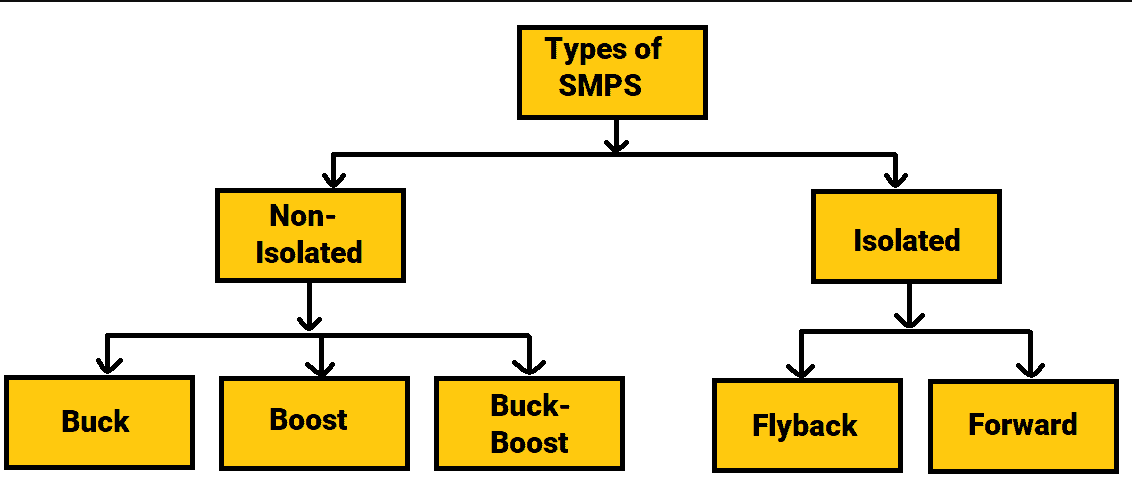
Non-isolated
Non-isolated converters are mostly used when the change in the voltage is comparatively small. Non-isolated SMPS have input and output circuits that are not isolated from one another. Its main drawback is that it cannot defend against high electrical voltages and generates more noise. There are three sorts of them.
1: Buck
The Buck switching regulator is a sort of switch-mode power supply circuit that is built to efficiently reduce DC voltage from a higher to a lower voltage by subtracting or "Bucking" the supply voltage, lowering the voltage available at the output terminals without affecting the polarity. In other terms, a buck switching regulator is a step-down regulator circuit that can transform +12 volts to +5 volts, for example.
A DC-to-DC converter, the buck switching regulator is one of the most basic and widely used switching regulators. The buck switching regulator employs a series transistor or power MOSFET (preferably an insulated gate bipolar transistor, or IGBT) as its principal switching device when utilised in a switch-mode power supply system, the circuit diagram of SMPS is shown below.

2: Boost
The Boost switching regulator is another type of switch-mode power supply circuit. It has the same components as the previous buck converter, however, they are arranged differently this time. The boost converter adds to or "Boosts" the supply voltage, so increasing the available voltage at the output terminals without affecting the polarity. In other terms, the boost switching regulator is a step-up regulator circuit, allowing a boost converter to convert +5 volts to +12 volts, for example.
A series switching transistor is used in the fundamental construction of the buck switching regulator, as we saw earlier. The boost switching regulator differs in that it controls the output voltage from the switch mode power supply using a parallel-connected switching transistor.
As the transistor switch is effectively connected in parallel with the output, electrical energy only passes through the inductor to the load when the transistor is biased “OFF” (switch open) as shown.

3: Buck-Boost
Buck-Boost switching regulators combine buck and boost converters to create an inverted (negative) output voltage that can be larger or less than the input voltage depending on the duty cycle. The buck-boost converter is a boost converter variant in which the inverting converter only sends the energy stored in the inductor, L1, to the load. The basic buck-boost switch mode power supply circuit is given below.

2: Isolated
Isolated SMPS are those that provide isolation between the input and output circuits The supplies make use of a transformer to separate the switching from the output. The transformer's secondary winding serves as an energy storage element.
I: Fly-back Converter:
The flyback design is simply a buck-boost design with the storage inductor replaced by a transformer. The transformer not only offers isolation but also allows the output voltage to be modified by adjusting the turns ratio. Multiple outputs are available since a transformer is involved. For low-power applications, the flyback is the simplest and most popular isolated design. While they are well adapted for high output voltages, the peak currents are quite high, and the structure is not well suited for output currents of more than 10A.
The flyback design has a benefit over other isolated topologies in that it does not require a separate storage inductor. There is no need for a separate inductor because the flyback transformer serves as the storage inductor. The flyback design is a cost-effective and popular topology because of this, as well as the fact that the majority of the circuitry is simple.
II: Forward Converter
The forward converter is really just a transformer isolated buck converter. The forward converter, like the flyback design, is ideally suited for low-power applications. While it has similar efficiency as the flyback, it has the drawback of having an additional inductor on the output and is not well suited for high voltage outputs. When large output currents are required, the forward converter has an advantage over the flyback converter. It is ideally suited for situations where the current is in excess of 15A since the output current is non-pulsing.
SMPS PINOUT
Generally the SMPS have four pins, two for output as well as for input whether it is a 12V SMPS or a 5V SMPS and many others. The SMPS may have more than two outputs as well.
|
S. No. |
PIN NAME |
Description |
|
1 |
IN+ |
Supply positive Voltage. |
|
2 |
IN- |
Should be connected to the GND supply. |
|
3 |
OUT+ and OUT- |
These are the output terminals present in SMPS to get the output voltage. |
What does a power supply tester do?
A power supply tester is an electronic device used to test how well a computer power supply is functioning. This type of testing is often performed as part of maintenance on a computer and can be used to try to determine the source of a computer problem.
Why Switch Mode Power Supply is better than Linear Power Supply?
|
PARAMETERS |
LINEAR POWER SUPPLY |
SWITCH MODE POWER SUPPLY (SMPS) |
|
Efficiency |
Low efficiency i.e. about 20-25% |
High Efficiency i.e. about 60-65% |
|
Weight |
It is bulky. |
It is less bulky in comparison to the linear power supply. |
|
Size |
Bigger size as compared to SMPS |
Small size than LPS |
|
Durability |
Less Durable |
More Durable |
|
Cost |
Costs more |
Cost’s less than Linear power supply |
FOR PURCHASING SMPS(click on SMPS):