

Latching Solenoid Valve
Solenoid valve is an electro-mechanical device/valve used to control the flow of liquid or gas. They are widely used in the most varied types of industries, plants and whenever fluid flow has to be controlled automatically. Solenoid includes a plunger surrounded by a coil, which when energized moves the plunger and provides a flow path for fluid.
Solenoid valves are like control units or switches and hence are suitable to be used in remote locations where manually controlling a valve is difficult or not at possible. There has been a significant rise in the use of solenoid valves.
There are various types of solenoid valve depending upon the mode of actuation, or number of flows paths (inlets and outlets), normally open or normally closed and bi-stable (also called latching solenoid valves). We will focus only on latching solenoid valve; you can read more about solenoid valves here https://www.omega.com/en-us/resources/valves-technical-principles
Normally closed solenoid valves are in closed position when there is no excitation, and open when there is a continuous current flow through the coil. Whereas latching/bi-stable solenoid valves have two stable position and utilizes a current pulse to switch between open and close position. Latching solenoid valves maintain the position of plunger even when there is no current supply and consume no power, generates no heat and no electrical noise/hum compared to conventional solenoid valves. Hence, latching solenoid valves are well suited for applications with power constraints or which are battery powered.

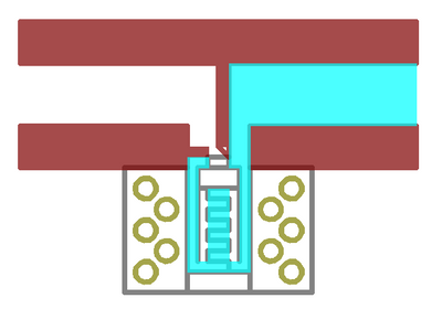
Latching solenoid valve uses a coil with a permanent magnet. When the coil is excited by short current pulse, a magnetic flux is added to that of the permanent magnet moving the plunger. After the pulse is removed the magnetic flux of the permanent magnet holds the plunger in position, opening the flow path or latching the plunger. To close the flow path a negative or reverse polarity current pulse is supplied across the coil which generates a magnetic flux cancelling that of the permanent magnet and the spring releases the plunger to closed or de-latched position.
How to use a bi-stable solenoid valve
Using H-Bridge
Latching solenoid valve requires a positive and negative current pulse to switch on and off, to provide this pulse the most common and reliable solution is a H-Bridge.

The above circuit diagram represents a H-Bridge utilizing complimentary pair of MOSFETs. A, D are P-MOS (recommended Si2301) and B, C are N-MOS (recommended Si2302). R5, R6, R7, R8 are used to remove humming or HF oscillations on the control pin and can be removed. R1, R2, R3, R4 are used to fast discharge the MOSFETs. Diodes D1, D2, D3, D4 are used to dissipated the stored energy in the coil when the valve supply is turned off.


To switch on the valve a positive pulse of 25ms is required (this is with reference to the valve- Solenoid Valve 1/2" DC 3.6-6V Water Control Electric Pulse) (please refer to the datasheet of the valve to check the required pulse duration), this is achieved by turning on the MOSFETs D (which is connected to the positive end of the valve, red wire of the valve) and B for 25ms. After that the valve is opened and will continuously allow the fluid flow. To turn off the valve the MOSFETs A and C are turned on for 25ms providing the negative current pulse.

When the valve is turned on or off a high current goes through the valve, to avoid supply voltage drop, capacitors C1 and C2 are used across the MOSFETs.
H-Bridge drivers which uses Darlington pair or BJT for switching are not suitable (like L293/L293D) to drive the bi-stable solenoid valve with 5V supply due to high internal voltage drop. Whereas MOSFETs based H-bridge drivers like DRV8833 can be easily used.
Using SPDT Relays
SPDT relays can be used as a two-way switch and are easy to operate with a very little connection overhead. The circuit diagram using two relays is shown below

When both the relays are off, there is no current going through the valve. Initially both the relays are in normally closed position. To turn the valve on, RELAY1 is switched from NC to NO for 25ms, providing the positive current pulse through the valve. To turn the valve off, RELAY2 is switched from NC to NO for 25ms, de-latching the valve to closed position. The positive and negative pulse flow is shown in the accompanying diagrams.


Solenoid valve applications
Solenoid valves can be used whenever fluid flow is to be controlled. They are used in
- Refrigerators, air conditioners.
- Water treatment plants and purifiers.
- Washing machines, dishwashers.
- Irrigation systems with automatic controls.
- Public toilets for automatic flushing.
- Medical equipment where flow of different medicines is to be controlled.
- Overhead water tanks.
2 comments
Bhaskar
What are the specifications of MOSFETs, remaining components in the circuit please
Pallab Mallick
I want to know how can I control a latching solenoid valve remotely?