

Today, in this blog I'm going to give you an overview of the applications of BD139 and BD140. This blog is the continuous blog of the series of transistors so if you wish to read about any other transistors then you may click HERE.
BD139

The BD139 is an NPN transistor, the collector and emitter will be open (reverse biased) while the base pin is grounded and closed (forward biased) when a signal is applied to the base pin. The BD139 is designed to especially used in audio applications.
The gain value of BD139 is a maximum 250, and this number defines the transistor's amplification capacity. Because the maximum current that may flow through the Collector pin is 1.5A, we cannot connect loads that use more than 1.5A to this transistor. To bias a transistor, we must give current to the base pin; this current (IB) should not exceed 0.5A.
BD140

The BD140 is a well-known PNP-type transistor that is utilized in many electronic circuits. The transistor can handle currents of up to 1.5A or 1500mA, allowing it to drive loads of up to 1.5A in electronic circuits such as high-power LEDs, relays, motors, and more. In addition to these features, it has a high collector-emitter voltage of 100 Volts and collector-base voltage of 80 volts, making it an ideal transistor to use in circuits that use 80 volts DC or less.
Furthermore, the collector dissipation of this transistor is roughly 12.5 watts, making it an excellent transistor for use in audio amplifier circuits. The transistor's minimum base voltage or saturation voltage is 0.5V.
 |
 |
Specifications

APPLICATIONS:
| BD140 AS A SWITCH | BD139 AS A SWITCH |
 |
 |
|
BD140 transistor is used as a switch, the current flows from the base. The base terminal of a PNP transistor is always negatively biased with respect to the emitter. In this connection, the load is connected to the transistor switching output with a reference point. When the transistor is activated, current travels from the source to the transistor, then to the load, and ultimately to the ground. |
When a transistor is used as a switch it is operated in the Saturation and Cut-Off Region. When we supply current to the transistor's base, it makes a path for the collector current to flow from the base to the emitter. During Forward Bias, the transistor will act as an Open switch, and during Reverse Bias, it will act as a Closed switch |
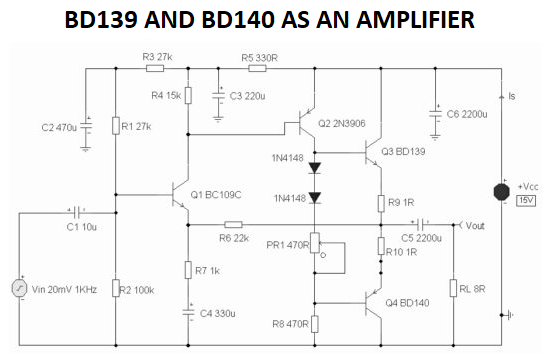 Now we'll go through how to use BD139 and BD140 as amplifiers in industrial and school projects.
- A 2-watt class-AB audio power amplifier with minimal harmonic distortion and wide frequency response is shown in a circuit schematic.
- It is capable of driving 8Ω speakers with 5-watt output power. The supply voltage in this circuit ranges between 12V and 18V.
- The potentiometer regulates the quiescent passes via BD139 and BD140 complementary transistors in this 470Ω circuit.
- Variations in this resistor's value represent a trade-off between minimal distortion and low current across the output transistors Q3 and Q4.
- Because this amplifier is DC-biased, the emitters of BD139 and BD1340 are set to roughly half the power supply voltage to allow for maximum output swing. Temperature stability is provided by extra R9 and R10 resistors in this circuit.
BD139 AND BD140 IN MOTOR DRIVER APPLICATION

This application is the H-Bridge Circuit which is used in motor driver circuits. When we need to operate DC motors, we need to give a large level of power to the motors, which the microcontroller cannot do alone, therefore we need to connect a transistor circuit between the controller and the motor, which acts as an amplifier and helps the motor run smoothly.
This H-bridge circuit provides enough power to drive two DC motors smoothly, and it also allows to adjust the direction of rotation of the motors. One thing to keep in mind when using BD139/140 or any other power transistor is that the power transistors generate a large amount of power, which is also generated in the form of heat, so in order to prevent overheating, we must add a heatsink to these transistors, for which a hole is already provided on the transistor.
After understanding the use cases of these transistors, if you wish to buy them then click down on their names.
BD139
BD140
Power Transistors