


Let's get started with this innovative Arduino tutorial where you will learn how to make a cool-looking Arduino Radar using an ultrasonic sensor. You can use Arduino radar to detect objects within a short distance. Obviously, this project is simple and enjoyable. This Radar system can be used in obstacle-avoiding robots.
Components Required:
What is HC-SR04 Sensor?
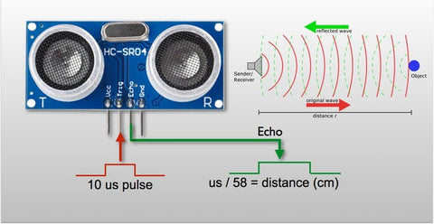
The HC-SR04 Ultrasonic Distance Sensor is made up of two cylindrical ultrasonic transducers. The one serves as a transmitter, converting electrical signals into ultrasonic sound pulses at a frequency of 40 kHz.It raises the echo pin after producing ultrasound, i.e. 8 pulses of 40 kHz. The echo pin stays high until the echo sound is no longer received. As a result, the width of the echo pin represents the time it takes for sound to travel to the object and return. Since we know the speed of sound, we can measure distance once we have the time.

The speed of sound is around 340 meters per second. This is equivalent to 29.412µs/cm. We use the formula Distance = (Time x Speed Of Sound) / 2 to calculate the distance travelled by sound.
Since the sound has to travel back and forth, the "2" is included in the formula. The sound first moves away from the sensor, then bounces off a surface and returns to the sensor. The formula Centimeters = ((Microseconds / 2) / 29 is a simple way to read the distance in centimeter.
The sensor is lightweight, simple to use in any robotics project, and provides excellent non-contact range detection with a 3mm accuracy between 2 cm and 400 cm (roughly an inch to 13 feet). It can be directly connected to an Arduino or some other 5V logic microcontroller since it runs on 5 volts.
Working of SG90 servo
 |
 |
A servo is made up of a DC motor, a potentiometer, a gear assembly, and a control circuit. To begin, we use a gear assembly to lower the RPM and increase the torque of the motor. Let's say the location of the potentiometer knob at the start of the servo motor shaft is such that no electrical signal is produced at the potentiometer's output port.
An electrical signal is now sent to the error detector amplifier's other input terminal. Now, the discrepancy between these two signals, one from the potentiometer and the other from another source, will be interpreted in the feedback system, and an error signal will be output. This error signal is used as the motor's input, and the motor begins to rotate. The potentiometer is now attached to the motor shaft, and as the motor rotates, so does the potentiometer, which generates a signal. If the angular location of the potentiometer varies, so does the output feedback signal.
Motor stops rotating when the external applied signal and signal generated at potentiometer become equivalent.
How to Interface SG90 servo motor with Arduino?
The PWM time for the tower pro servo motor is 20 milliseconds (in frequency domain 50 Hz). 50 Hz is the operating frequency (in time domain 20ms). To rotate the arm head, a PWM signal with a duration of 20ms and a signal duty cycle of 0 to 2ms must be produced.
- On a duty cycle of 1.5 milliseconds, the Tower Pro Micro Servo SG90 9g rotates to 90 degrees.
- On a 2ms duty cycle, it rotates 180 degrees.
- On a 1ms duty cycle, it moves to 0 degrees.
By changing the duty cycle, it is simple to rotate the arm at a fixed angle. At a duty cycle of 135 degrees, it will take 1.75 milliseconds to move the servo motor arm. The speed of the arm can be regulated by gradually changing the service cycle. If the duty cycle is increased by 2 milliseconds, the servo arm will not return to its original location and will be rendered inoperable.
Similar to how a radar approximates the objects surrounding its base station, this DIY project allows the user to visualize the objects that surround the motor and ultrasonic sensor. Several of the skills taught in this tutorial can be applied to real-world situations, such as obstacle detection, motor coordination, distancing and ranging, and even a new data visualization method.

Note: Make sure that you have Servo library installed in Arduino IDE.
Software setup
- Download and Install processing software from here
Copy the code given below into the processing software and Change the port with your Arduino port shown in Arduino IDE.
Codeimport processing.serial.*; // imports library for serial communication
import java.awt.event.KeyEvent; // imports library for reading the data from the serial port
import java.io.IOException;
Serial myPort; // defines Object Serial
// defubes variables
String angle="";
String distance="";
String data="";
String noObject;
float pixsDistance;
int iAngle, iDistance;
int index1=0;
int index2=0;
PFont orcFont;
void setup() {
size (1200, 700); // ***CHANGE THIS TO YOUR SCREEN RESOLUTION***
smooth();
myPort = new Serial(this,"COM11", 9600); // starts the serial communication
myPort.bufferUntil('.'); // reads the data from the serial port up to the character '.'. So actually it reads this: angle,distance.
}
void draw() {
fill(98,245,31);
// simulating motion blur and slow fade of the moving line
noStroke();
fill(0,4);
rect(0, 0, width, height-height*0.065);
fill(98,245,31); // green color
// calls the functions for drawing the radar
drawRadar();
drawLine();
drawObject();
drawText();
}
void serialEvent (Serial myPort) { // starts reading data from the Serial Port
// reads the data from the Serial Port up to the character '.' and puts it into the String variable "data".
data = myPort.readStringUntil('.');
data = data.substring(0,data.length()-1);
index1 = data.indexOf(","); // find the character ',' and puts it into the variable "index1"
angle= data.substring(0, index1); // read the data from position "0" to position of the variable index1 or thats the value of the angle the Arduino Board sent into the Serial Port
distance= data.substring(index1+1, data.length()); // read the data from position "index1" to the end of the data pr thats the value of the distance
// converts the String variables into Integer
iAngle = int(angle);
iDistance = int(distance);
}
void drawRadar() {
pushMatrix();
translate(width/2,height-height*0.074); // moves the starting coordinats to new location
noFill();
strokeWeight(2);
stroke(98,245,31);
// draws the arc lines
arc(0,0,(width-width*0.0625),(width-width*0.0625),PI,TWO_PI);
arc(0,0,(width-width*0.27),(width-width*0.27),PI,TWO_PI);
arc(0,0,(width-width*0.479),(width-width*0.479),PI,TWO_PI);
arc(0,0,(width-width*0.687),(width-width*0.687),PI,TWO_PI);
// draws the angle lines
line(-width/2,0,width/2,0);
line(0,0,(-width/2)*cos(radians(30)),(-width/2)*sin(radians(30)));
line(0,0,(-width/2)*cos(radians(60)),(-width/2)*sin(radians(60)));
line(0,0,(-width/2)*cos(radians(90)),(-width/2)*sin(radians(90)));
line(0,0,(-width/2)*cos(radians(120)),(-width/2)*sin(radians(120)));
line(0,0,(-width/2)*cos(radians(150)),(-width/2)*sin(radians(150)));
line((-width/2)*cos(radians(30)),0,width/2,0);
popMatrix();
}
void drawObject() {
pushMatrix();
translate(width/2,height-height*0.074); // moves the starting coordinats to new location
strokeWeight(9);
stroke(255,10,10); // red color
pixsDistance = iDistance*((height-height*0.1666)*0.025); // covers the distance from the sensor from cm to pixels
// limiting the range to 40 cms
if(iDistance<40){
// draws the object according to the angle and the distance
line(pixsDistance*cos(radians(iAngle)),-pixsDistance*sin(radians(iAngle)),(width-width*0.505)*cos(radians(iAngle)),-(width-width*0.505)*sin(radians(iAngle)));
}
popMatrix();
}
void drawLine() {
pushMatrix();
strokeWeight(9);
stroke(30,250,60);
translate(width/2,height-height*0.074); // moves the starting coordinats to new location
line(0,0,(height-height*0.12)*cos(radians(iAngle)),-(height-height*0.12)*sin(radians(iAngle))); // draws the line according to the angle
popMatrix();
}
void drawText() { // draws the texts on the screen
pushMatrix();
if(iDistance>40) {
noObject = "Out of Range";
}
else {
noObject = "In Range";
}
fill(0,0,0);
noStroke();
rect(0, height-height*0.0648, width, height);
fill(98,245,31);
textSize(25);
text("10cm",width-width*0.3854,height-height*0.0833);
text("20cm",width-width*0.281,height-height*0.0833);
text("30cm",width-width*0.177,height-height*0.0833);
text("40cm",width-width*0.0729,height-height*0.0833);
textSize(40);
text("HatchnHack ", width-width*0.875, height-height*0.0277);
text("Angle: " + iAngle +" °", width-width*0.48, height-height*0.0277);
text("Distance: ", width-width*0.26, height-height*0.0277);
if(iDistance<40) {
text(" " + iDistance +" cm", width-width*0.225, height-height*0.0277);
}
textSize(25);
fill(98,245,60);
translate((width-width*0.4994)+width/2*cos(radians(30)),(height-height*0.0907)-width/2*sin(radians(30)));
rotate(-radians(-60));
text("30°",0,0);
resetMatrix();
translate((width-width*0.503)+width/2*cos(radians(60)),(height-height*0.0888)-width/2*sin(radians(60)));
rotate(-radians(-30));
text("60°",0,0);
resetMatrix();
translate((width-width*0.507)+width/2*cos(radians(90)),(height-height*0.0833)-width/2*sin(radians(90)));
rotate(radians(0));
text("90°",0,0);
resetMatrix();
translate(width-width*0.513+width/2*cos(radians(120)),(height-height*0.07129)-width/2*sin(radians(120)));
rotate(radians(-30));
text("120°",0,0);
resetMatrix();
translate((width-width*0.5104)+width/2*cos(radians(150)),(height-height*0.0574)-width/2*sin(radians(150)));
rotate(radians(-60));
text("150°",0,0);
popMatrix();
}
Arduino Code
#include <Servo.h>.
// Defines Tirg and Echo pins of the Ultrasonic Sensor
const int trigPin = 10;
const int echoPin = 9;
// Variables for the duration and the distance
long duration;
int distance;
Servo myServo; // Creates a servo object for controlling the servo motor
void setup() {
pinMode(trigPin, OUTPUT); // Sets the trigPin as an Output
pinMode(echoPin, INPUT); // Sets the echoPin as an Input
Serial.begin(9600);
myServo.attach(3); // Defines on which pin is the servo motor attached
}
void loop() {
// rotates the servo motor from 0 to 180 degrees
for(int i=0;i<=180;i++){
myServo.write(i);
delay(30);
distance = calculateDistance();// For each degree, calls a function that calculates the distance measured by the Ultrasonic sensor.
Serial.print(i); // The current degree is sent to the Serial Port.
Serial.print(","); // Addition character is sent right next to the previous value, which is required for indexing later in the Processing IDE.
Serial.print(distance); // The value of the distance is sent to the Serial Port.
Serial.print("."); // Addition character is sent right next to the previous value, which is required for indexing later in the Processing IDE.
}
// Repeats the previous lines from 180 to 0 degrees
for(int i=180;i>0;i--){
myServo.write(i);
delay(30);
distance = calculateDistance();
Serial.print(i);
Serial.print(",");
Serial.print(distance);
Serial.print(".");
}
}
// The distance measured by the Ultrasonic sensor is calculated using this function.
int calculateDistance(){
digitalWrite(trigPin, LOW);
delayMicroseconds(2);
// For 10 microseconds, the trigPin is in the HIGH state.
digitalWrite(trigPin, HIGH);
delayMicroseconds(10);
digitalWrite(trigPin, LOW);
duration = pulseIn(echoPin, HIGH); // Returns the sound wave travel time in microseconds after reading the echoPin.
distance= duration*0.034/2;
return distance;
}