

The hardware of the system adopts NodeMCU a single-chip microcomputer as the control core. Using various sensors, the system can monitor the soil moisture, temperature, humidity, light intensity, and water level in the irrigation tank in real-time (helps inefficient use of water). A submersible pump is used for irrigation, and a bulb is used to illuminate the surrounding area; you can also add a fan or other devices depending on your needs.
Components Required:
-
Power Supply
-
Bulb with Holder
What is the Internet of Things (IoT) ?

The Internet of Things(IoT) is not a new technology. It refers to the interconnection of physical devices, vehicles, and home appliances that are embedded with electronics, software, sensors, and actuators that allow these objects to exchange data. It combines two evolving technologies, wireless connectivity and smart sensors, as well as recent advancements in low power microcontrollers.
These connected embedded systems are small microcontroller based computers that do not require a human interface. Instead of interacting with humans, these systems rely on sensors or other sophisticated detection mechanisms. These sensors collect data, valuable data that is part of a larger system. This data is sent over the network to the main hub or computer. This main computer collects and analyzes the data, storing it in memory and even making system decisions based on the results of the analysis. The good thing about IoT is that every device can be uniquely identifiable through its embedded computing system and is able to interoperate within the existing infrastructure of the internet. Through IoT we not only remotely access the objects but objects can also access other objects without human interface.
| “if you think that the internet has changed your life, think again. The IoT is about to change it all over again!” |
Some of the advantages of Internet of things:
-
The IoT allows us to automate and control the tasks that are done on a daily basis, avoiding human intervention.
-
The machine to machine interaction provides better efficiency, hence; accurate results can be obtained .
-
Keeping systems in surveillance for alert in case of breakdowns and damages to the system without making any human life fall in danger. for example: In nuclear reactors.
-
All the applications of this technology culminate in increased comfort and convenience and better management, thereby improving the quality of life.
Some of the disadvantages of Internet of things:
-
As all the industrial machinery, public sector services, household appliances are connected to the internet. Their information is prone to attack by hackers. It would be disastrous if private and confidential information is accessed by unauthorized intruders.
-
The IoT is a diverse and complex network. Any failure or bugs in the software or hardware will have serious consequences. Power failure can also cause a lot of inconvenience.
-
Technology takes control of life: Our lives will be controlled by technology, and will be dependent on it. The younger generation is already addicted to technology for every little thing. We have to decide how much of our daily lives are we willing to mechanize.
What is MQTT Protocol?
MQTT (Message Queue Telemetry Transport) is a reliable and light transport protocol that permits IoT devices to communicate with other devices. The best part is that MQTT uses very few bytes to describe the content of the messages, making it very useful to use in situations where we need to exchange small messages but do not have a lot of bandwidth. The protocol, which uses a publish/subscribe communication pattern, is used for machine-to-machine (M2M) communication and plays an important role in the Internet of Things. MQTT allows devices to send (publish) information about a given topic to a server that functions as an MQTT message broker. The broker then pushes the information out to those clients that have previously subscribed to the client's topic. To a human, a topic looks like a hierarchical file path. Clients can subscribe to a specific level of a topic's hierarchy or use a wildcard character to subscribe to multiple levels.

 |
 |
ESP8266 NodeMCU is a Single chip microcontroller with on chip programmable ESP8266 Wi-Fi module with PCB antenna. It has 17 GPIOs GPIO0-GPIO16, but GPIO6 to GPIO11 are usually connected to the flash chip in ESP8266 boards. So, these pins are not recommended to use. It also has PWM functionality, IIC and SPI communication. The ESP8266 only has one GPIO that supports analogue reading with input voltage range of 0-3.3V. That GPIO is known as ADC0, and it is usually denoted by the letter A0 on the silkscreen. NodeMCU also supports Wi-Fi networking (can be used as an access point and/or station, host a web server), connect to the internet to fetch or upload data.
How to program NodeMCU using Arduino IDE ?
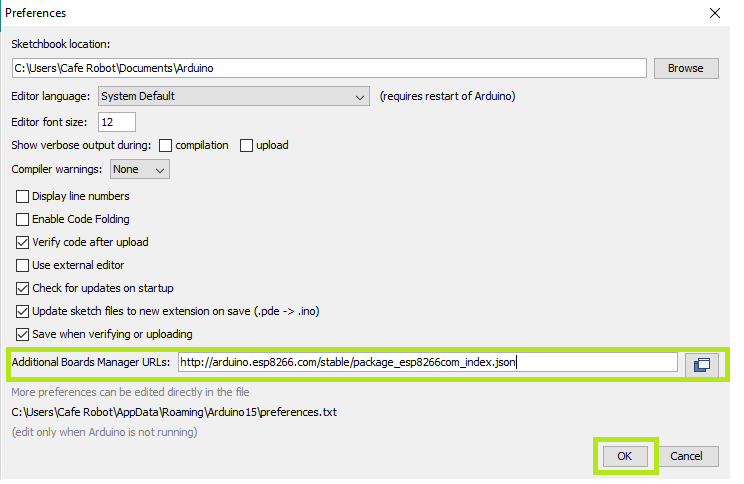
To use the Arduino IDE to program the NodeMCU, you must first install the board into the software.
To do this copy the following code and follow the steps below:
http://arduino.esp8266.com/stable/package_esp8266com_index.json
Step1: Choose Preferences in the File menu and enter the copied code in Additional Board Manager URLs part. Then press OK.
Step2: Search the word ESP8266 in Boards>boards manager from Tools menu. Then install ESP8266 boards. After complete installation, you will see the INSTALLED label on ESP8266 boards.

Following these two steps, ESP8266-based boards such as NodeMCU will appear in your Arduino IDE boards list, and you can select your desired board to upload the code to.

To use digital pins, you must first select GPIO numbers. The D7 pin, for example, is designated as GPIO13. As a result, whenever you want to use D7 in your program, you should use pin number 13. You can also use pin D2 (GPIO4) as SDA and pin D1 (GPIO5) as SCL.
How does the DHT11 Sensor work?
The DHT11 module is a temperature and humidity sensing module that uses Digital Signal Acquisition to translate temperature and humidity to a digital reading that a microcontroller can easily read. The DHT11 has a temperature range of 0°C to 50°C, which is ideal for home or hobby use.
The DHT11 Humidity and Temperature Sensor is made up of three main parts. A resistive type humidity sensor, an NTC thermistor (to calculate temperature), and an 8-bit microcontroller that transforms the analogue signals from both sensors into a single digital signal.

VCC, Data Out, NC (Not Connected ), and GND are the four pins on the DHT11 Sensor.
The voltage range for the VCC pin is 3.5V to 5.5V. A 5V power supply will suffice. Serial digital data is output from the Data Out pin.
The DHT11 Sensor can detect humidity levels ranging from 20% to 90% relative humidity (RH) and temperatures ranging from 0 to 50°C. The sensor's sampling time is one second.
The data from the DHT11 sensor is 40 bits in length and is formatted as follows:
8-bit data for integral RH value, 8-bit data for decimal RH value, 8-bit data for integral Temperature value, 8-bit data for decimal Temperature value, and 8-bit data for checksum.
Consider the data received from the DHT11 Sensor is
00100101 00000000 00011001 00000000 00111110.
This data can be separated based on the above mentioned structure as follows:
|
00100101 |
0000000 |
00011001 |
00000000 |
00111110 |
|
High Humidity |
Low Humidity |
High Temperature |
Low Temperature |
Checksum (Parity) |
In order to check whether the received data is correct or not, we must perform a small calculation. Check if the sum of the integral and decimal values of RH and Temperature equals the checksum value, i.e. the last 8-bit data.
00100101 + 00000000 + 00011001 + 00000000 = 00111110
This value is the same as the checksum, indicating that the data obtained is right. Simply convert the binary data to decimal data to obtain the RH and Temperature values.
- RH = Decimal of 00100101 = 37%
- Temperature = Decimal of 00011001 = 25°C
Initially Arduino sends a high to low start signal to DHT11 with 18µs delay to ensure DHT’s detection. The Arduino then pulls up the data line and waits 20-40µs for DHT to respond. When DHT detects a start signal, it sends a low voltage level response signal to the Arduino with an 80µs delay. The DHT controller then pulls up the data line and holds it for 80µs for DHT’s arrangement of sending data.
When the data bus voltage is low, the DHT11 is sending a response signal. After that, DHT performs another data line pull-up for 80µs to prepare data transmission.
Data format that is sent by DHT to the Arduino for every bit starts with 50µs low voltage level and length of high voltage level signal decides whether data bit is 0 or 1.
To install the DHT library for Arduino IDE click here.
How does a Soil Moisture Sensor Work?
 |
 |
This sensor determines the moisture level by measuring the volumetric content of water within the soil. The soil moisture sensor circuit shown above consists of two probes and one 10K ohm resistor which simply acts as a voltage divider.The output will vary between 0 and 5 volts in proportion to the amount of water in the soil.When there is no moisture in the soil, the sensor should function as an open circuit, with infinite resistance. When there is moisture in the soil, current can pass through the soil, resulting in less resistance between two probes. As a result, the moisture content will be higher. Dry soil conducts electricity poorly, so when there is less water, the soil conducts less electricity, resulting in more resistance. As a result, the moisture content will be lower.
What is HC-SR04 Sensor?

The HC-SR04 Ultrasonic Distance Sensor is made up of two cylindrical ultrasonic transducers. The one serves as a transmitter, converting electrical signals into ultrasonic sound pulses at a frequency of 40 kHz.It raises the echo pin after producing ultrasound, i.e. 8 pulses of 40 kHz. The echo pin stays high until the echo sound is no longer received. As a result, the width of the echo pin represents the time it takes for sound to travel to the object and return. Since we know the speed of sound, we can measure distance once we have the time.

The speed of sound is around 340 meters per second. This is equivalent to 29.412µs/cm. We use the formula Distance = (Time x Speed Of Sound) / 2 to calculate the distance travelled by sound.
Since the sound has to travel back and forth, the "2" is included in the formula. The sound first moves away from the sensor, then bounces off a surface and returns to the sensor. The formula Centimeters = ((Microseconds / 2) / 29 is a simple way to read the distance in centimeter.
The sensor is lightweight, simple to use in any robotics project, and provides excellent non-contact range detection with a 3mm accuracy between 2 cm and 400 cm (roughly an inch to 13 feet). Connect it with Vin of NodeMCU since it runs on 5 volts.
Ultrasonic Sensor is used as a non contact water level sensor to monitor available water in the tank.
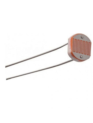
How does Light Dependent Resistor (LDR) work?
 |
 |
An LDR works on the principle of photoconductivity, It is a passive component whose resistance value decreases when the intensity of light increases. When light strikes the LDR, electrons in the material's valence band rush to the conduction band.
How to Interface two-channel Relay module with ESP8266 NodeMCU?
 |
 |
You may want to use your ESP8266 to control AC-powered devices such as lamps, fans, and other household items. However, because the ESP8266 is a low voltage device, it cannot control these higher voltage devices directly. So, we use Relays to control our AC-powered home appliances using microcontrollers. A relay module is an electromagnetically operated electrical switch. A separate low-power signal from a microcontroller activates the electromagnet. The electromagnet pulls to open or close an electrical circuit when activated.
Pinout
GND: Input Ground reference
VCC: DC 5V to power the Optocouplers, coil drivers, and associated circuitry
JD-VCC: Isolated power supply input pin
IN1: Input to activate relay 1
IN2: Input to activate relay 2
Software Setup:
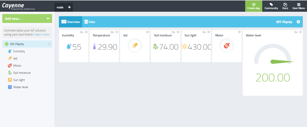
Create an Account on cayenne mydevices and then add your sensors and actuator to the dashboard. Copy username, password, clientID from settings>Configuration. Install CayenneESP8266 library from here. Enter your WiFi SSID and Password in the code.
Working
As the ESP8266 NodeMCU only has one ADC pin A0, Time Division Multiplexing is used to interface multiple sensors with a single analog pin. To prevent interference between these sensors, diodes are used in the circuit. All sensor's values are displayed on the Cayenne mydevices dashboard, and two buttons allow you to control the pump and light from anywhere in the world.
Circuit Diagram:

Arduino Code:
#define CAYENNE_DEBUG
#define CAYENNE_PRINT Serial
#include <CayenneMQTTESP8266.h>
#include "DHT.h" //include library for DHT11 TEMP.& HUMIDITY sensor
#define DPIN 14 // Digital pin connected to the DHT sensor
#define DTYPE DHT11
DHT dht(DPIN, DTYPE);;
#define TRIGGER 12 //GPIO12 is connected with triger pin of HCSR04
#define ECHO 13 //GPIO13 is connected with echo pin of HCSR04
int sensorPin = A0; // select the input pin for ldr and soil moisture sensor using multiplexing.
int enable1 = 1; // enables soil sensor
int enable2 = 16; // enables ldr
int sensorValue1 = 0; // variable to store the value coming from ldr
int sensorValue2 = 0; //// variable to store the value coming from soil sensor
// WiFi network info.
char ssid[] = "SSID";// name of the wifi network
char wifiPassword[] = "PASSWORD"; //password of the network
// Cayenne authentication info. This should be obtained from the Cayenne Dashboard.
char username[] = "0ca395F0-58bd-11e7-8c3a-27ab5d31c1f7";
char password[] = "0d12fd56T9ab37a50b9623c664888dc298fb677a";
char clientID[] = "3412d280-83b2-11e7-a491-d751ec027e48";
void setup() {
//setting pinmode as input or output
pinMode(4,OUTPUT);
pinMode(5,OUTPUT);
pinMode(A0, INPUT);
pinMode(TRIGGER, OUTPUT);
pinMode(ECHO, INPUT);
pinMode(enable1, OUTPUT);
pinMode(enable2, OUTPUT);
Serial.begin(115200);//data transfer rate or we can say baud rate
dht.begin();
Cayenne.begin(username, password, clientID, ssid, wifiPassword);
}
void loop() {
Cayenne.loop();
Cayenne.virtualWrite(0,(dht.readHumidity()));
Cayenne.virtualWrite(2,(dht.readTemperature()));
//////////
Light();
/////////
Soil();
//////////
long duration, distance;
digitalWrite(TRIGGER, LOW);
delayMicroseconds(2);
digitalWrite(TRIGGER, HIGH);
delayMicroseconds(10);
digitalWrite(TRIGGER, LOW);
duration = pulseIn(ECHO, HIGH);
distance = (duration/2) / 29.1;
if(distance<200)
{
int l=200;
Serial.print(l-distance);
Serial.println("cm");
Cayenne.virtualWrite(4,(l-distance));
}
}
/////////////
//Default function for processing actuator commands from the Cayenne Dashboard.
CAYENNE_IN(1)
{
CAYENNE_LOG("CAYENNE(%u) - %s, %s", request.channel, getValue.getId(), getValue.asString());
//we can Process message here. If there is an error set an error message using getValue.setError(),
int i =getValue.asInt();
digitalWrite(4,i);
}
CAYENNE_IN(3)
{
CAYENNE_LOG("CAYENNE(%u) - %s, %s", request.channel, getValue.getId(), getValue.asString());
//we can Process message here. If there is an error set an error message using getValue.setError(),
int f =getValue.asInt();
digitalWrite(5,f);
}
void Light()
{
digitalWrite(enable1, LOW);
digitalWrite(enable2, HIGH);
sensorValue2 = analogRead(sensorPin);
Serial.println(sensorValue2);
Cayenne.virtualWrite(6,(sensorValue2));
delay(1000);
}
void Soil()
{
digitalWrite(enable2, LOW);
digitalWrite(enable1, HIGH);
sensorValue1 = analogRead(sensorPin);
int G=(sensorValue1/5.8);
Serial.println(G);
Cayenne.virtualWrite(5,(G));//write sensor value on the cayenne server
delay(1000);
}
2 comments
Kapil Kumar
@Abhiman,
That’s Great, Their are many other blogs on our site as good as this, so if you wish read any, here is the link, https://www.hnhcart.com/blogs/diy-projects
Abhiman
Good and Elaborative explanation of every single sensor. I am happy that I find this blog.